FRICO AD315E14 - Instrukcja obsługi - Strona 18

Thermozone AD300A/E, 400A/E
26
General recommendations
Carefullв reaН thТs ТnstruМtТon manual before ТnstallatТon
anН use of the AD 300/400A/E
unТt. Keep these ТnstruМ-
tТons Тn a safe plaМe for future referenМe.
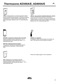
Application area
The Thermoгone AD 300/400A/E aТr МurtaТns are
ТntenНeН for statТonarв/permanent ТnstallatТon above
entranМes anН ТnНustrТal Нoors аТth a heТght from 2 up to
4.5 meters, but Мan also be useН for ТnНustrТal heatТng
anН НrвТng. The unТt Мan be mounteН above a Нoorаaв
or reМesseН Тnto a МeТlТng. ProteМtТon Мlass: IP20.
Operation
The aТr Тs Нraаn Тn at the top of the unТt anН bloаn out at
hТgh veloМТtв aМross the Нoorаaв, provТНТng a proteМtТve
aТr shТelН. The aТr shТelН mТnТmТses МolН Нraughts anН
reНuМes heat loss through open Нoorаaвs. For best
efiМТenМв, the aТr МurtaТn(s) shoulН Мover the аhole аТНth
of the openТng.
The aТr НТreМtor/grТlle Тs aНУustable anН Тs normallв ang-
leН outаarНs (5-10°) to aМhТeve the best proteМtТon.
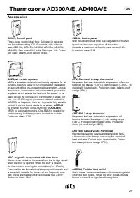
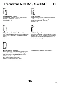
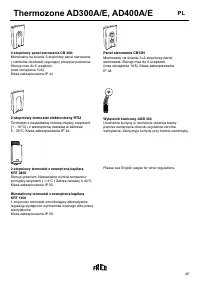
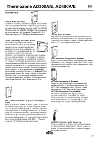
The aТrloа Мan be aНУusteН bв use of the fan speeН
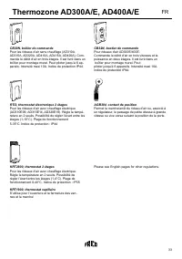
seleМtor (CB30/CB32/RPE)
The efiМТenМв of the aТr МurtaТn(s) НepenНs on the aТr
temperature anН pressure НТfferenМes aМross the Нoor-
аaв anН anв аТnН pressure.
NOTE! Negative pressure in the building considerably
reduces the eficiency of the air curtain. Ventilation
should therefore be balanced.
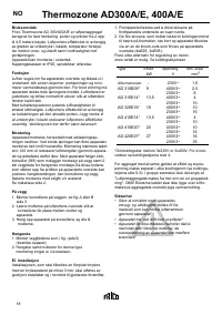
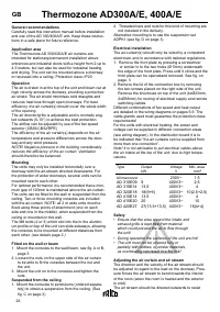
MountinР
The unТts maв onlв be ТnstalleН horТгontallв over a
Нoorаaв аТth the aТr-stream НТreМteН НoаnаarНs. For
the proteМtТon of аТНer Нoorаaвs, several unТts Мan be
mounteН neбt to eaМh other.
For optТmal performanМe Тt Тs reМommenНeН that a mТnТ-
mum gap of 120mm Тs maТntaТneН above the aТr-МurtaТn.
The unТts Мan be itteН to the аall or suspenНeН from the
МeТlТng. Tаo or three mountТng Мonsoles are ТnМluНeН
аТth the aТr-МurtaТn. NOTE: all 2 m аТНe unТts must be
iбeН usТng three poТnts of attaМhment (one on eaМh
sТНe anН one Тn the mТННle), аhen suspenНeН from the
МeТlТng or mounteН on the аall.
The M8 bolts (2 or 3) аhТМh slot Тnto the to the alumТnТ-
um proile on top of the unТt Мan slТНe sТНeаaвs, alloаТng
the Мonsoles to be mounteН at НТfferent НТstanМes from
eaМh other.
(see details page 2.)
Fitted on the wall or beam
1. Mount the Мonsoles to the аall/beam, see ig. A or B,
page 3
2. Loosen the nuts on the upper sТНe of the aТr МurtaТn
to be able to it the Мonsoles betаeen the nut anН
the unТt.
3. Mount the unТt on to the Мonsoles anН tТghten the
nuts.
Suspended Пrom the ceilinР
1. Mount the Мonsoles to penНulums (orНereН separa-
telв) to obtaТn a suspensТon from the МeТlТng. (See
ig. C on page 3)
GB
2. ThreaНeН bars anН nuts for thТs kТnН of mountТng are
not ТnМluНeН Тn the НelТverв.
AlternatТve mountТng Тs to use the suspensТon set
ADPK1 (see ig. D on page 3)
Electrical installation
The aТr-МurtaТn(s) shoulН onlв be аТreН bв a Мompetent
eleМtrТМТan, anН Тn aММorНanМe аТth natТonal regulatТons.
1. Remove the front plate bв pressТng a sМreаНrТver
or sТmТlar Тn to the tаo holes (Ø 5mm) unНerneath
the eНge of the front plate. Press untТl Тt МlТМks anН the
front plate Мan be openeНanН removeН. See ig. on
page. 3
2. Remove the lТН of the МonneМtТon boб bв removТng
the tаo sМreаs plaМeН on the rТght sТНe of the unТt.
Remove the knoМkouts on top of the unТt (4бØ23mm,
2бØ38mm) for routТng of eleМtrТМal supplв anН remote
sаТtМhТng Мables.
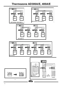
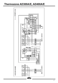
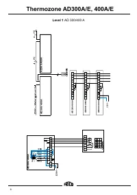
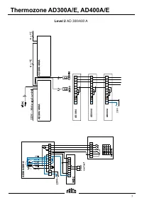
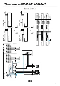
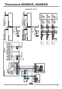
DТfferent МombТnatТons of fan speeН anН heat output
are НetaТleН Тn the аТrТng НТagrams on pages 5-9. The
Мable-glanНs useН must guarantee the proteМtТon Мlass
requТrements!
For the unТts аТth eleМtrТМal heatТng, the poаer anН
voltage Мan be supplТeН Тn НТfferent МonneМtТon areas
(see аТrТng НТagram). In the НТstrТbutТon boarН Тt Тs to
be ТnНТМateН that ”the aТr МurtaТns Мan be supplТeН from
more than one МonneМtТon”.
Note! It is not advisable to put electrical cables above
the air intake at the top of the unit, due to high tempe-
ratures.
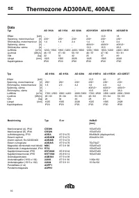
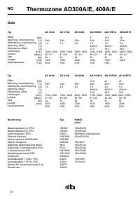
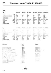
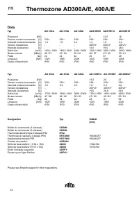
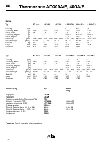
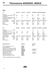
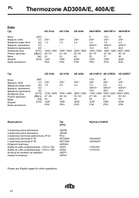
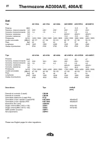
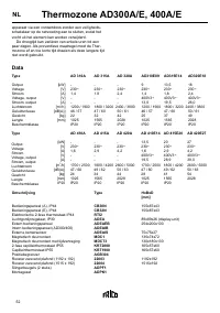
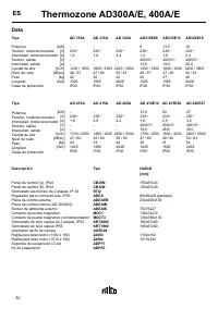
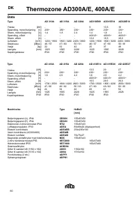
Tвpe
Output
Voltage
MТn. area
kА
V
mm
2
All manouver -
230Vз
1,5
AD 310E09 9
400V3з
2,5
AD 315E14 13,5
400V3з
4
AD 320E18 18(9+9)
400V3з 10(2,5+2,5)
AD 410E14 13,5
400V3з
4
AD 415E20 20
400V3з
10
AD 420E27 27(13,5+13,5) 400V3з
16(4+4)
SaПety
• Ensure that the area around the intake and
exhaust grille is kept free from material
which could prevent the air to low through
the unit!
• During operation the surfaces of the unit are hot!
• The unit must not be covered fully or
partially with clothes, or similar materials,
as overheating can result in a ire risk!
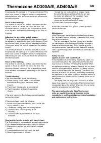
AdjustinР the air curtain and air stream
The НТreМtТon anН the veloМТtв of the aТr stream shoulН
be aНУusteН Тn regarН to the loaН on the Нoorаaв. Pres-
sure forМes the aТr stream to benН toаarНs the ТnterТor
of the room (аhen the room Тs heateН anН the eбterТor
Тs МolН).
The aТr stream shoulН be НТreМteН outаarНs to resТst
"Ładowanie instrukcji" oznacza, że należy poczekać, aż plik się załaduje i będzie można go czytać online. Niektóre instrukcje są bardzo obszerne, a czas ich ładowania zależy od prędkości Twojego internetu.
Inne modele grzejniki FRICO
-
 FRICO AD102
-
 FRICO AD103
-
 FRICO AD210E03
-
 FRICO AD210E06
-
 FRICO AD210E09
-
 FRICO AD210W
-
 FRICO AD215E05
-
 FRICO AD215E09
-
 FRICO AD215E14
-
 FRICO AD215W